
In brief
- FMECA answers what can fail, how it fails and how severe that failure is. RCM takes that output and answers a different question: what is the right thing to do about each failure mode, and is doing anything worth the cost at all.
- Run properly they are not two separate exercises but a single analytical process with two distinct roles, one feeding the other.
- What separates a strategy that holds up in an audit from one that falls apart under scrutiny is rarely the methodology. It is how precisely each element inside it is written.
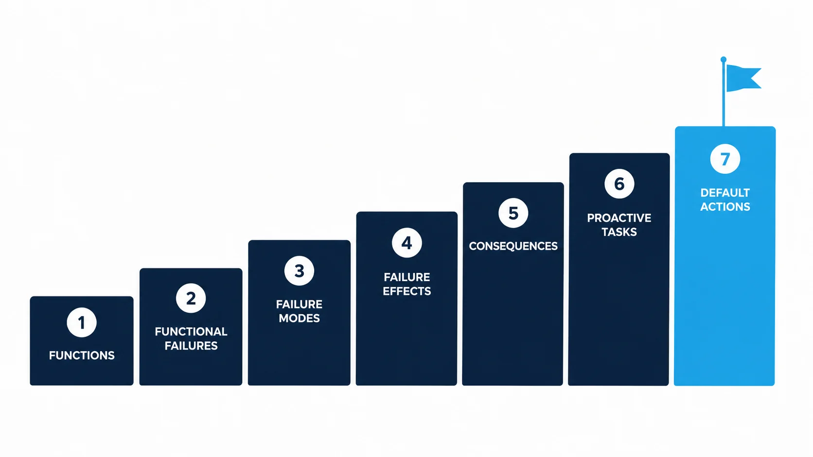
- RCM is seven specific questions answered in a fixed sequence, and the value of the whole exercise depends on how precisely each one is answered.
- This piece works through both methodologies as one process, carrying a single worked example, a pump bearing, from the smallest component up to the consequence a business actually experiences.
Ask most maintenance planners why a bearing gets greased every 500 hours, or why a valve gets overhauled every two years, and the honest answer is rarely an engineering one. It is that's what the OEM manual says, or that's what the last planner set up, or that's the interval sitting in the system we inherited. None of those answers explain what actually fails, what happens when it does, or whether the task does anything to stop it. Failure Mode, Effects and Criticality Analysis and Reliability Centred Maintenance exist to replace that guesswork with an answer that can be defended, line by line, to an engineer, an auditor or a board.
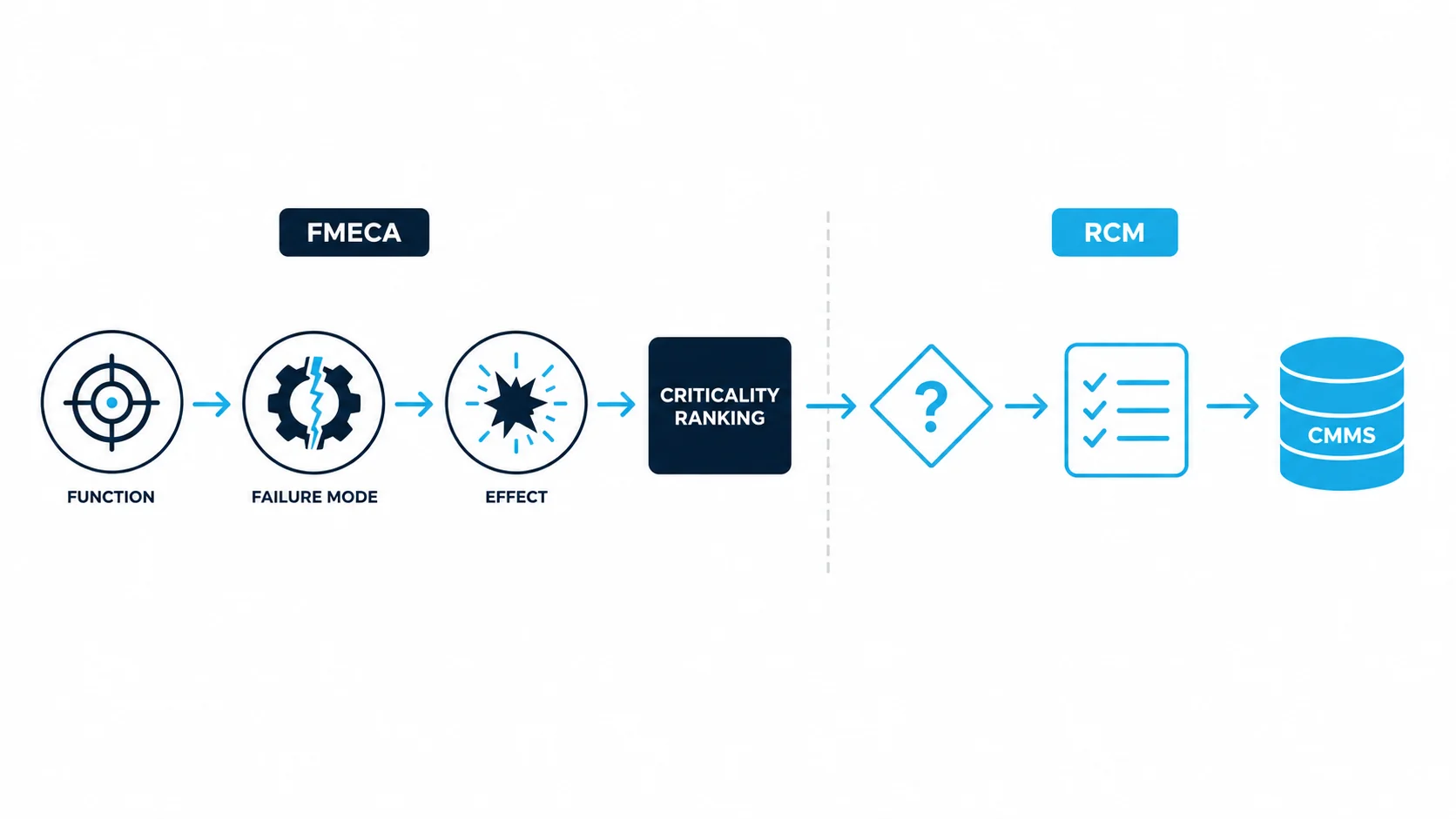
FMECA and RCM are frequently treated as two separate exercises: one a documentation task performed to satisfy a client specification, the other a maintenance philosophy applied loosely to whatever equipment gets labelled critical. Run properly, they are a single analytical process with two distinct roles. FMECA answers what can fail, how it fails, and how severe that failure is. RCM takes that output and answers a different question entirely: given everything FMECA has found, what is the right thing to do about each failure mode, and is doing anything worth the cost at all.
Most of what separates a strategy that holds up in an audit from one that quietly falls apart under scrutiny is not the methodology itself. It is how precisely each element inside it is written. A failure mode, a function, an effect or a task that is vague at the point of analysis stays vague all the way through to the work order, and a technician executing that work order cannot do consistently what was never described precisely in the first place. This piece works through both methodologies as one integrated process, with particular attention to how each element should actually be written: the seven questions RCM asks, the nomenclature that makes a failure mode analysable rather than a label, how that description changes as the analysis moves up through the asset hierarchy, and how a task instruction reaches the level of precision a technician can execute the same way every time.
Two Different Questions, One Analytical Process
FMECA and RCM sit at different points on the same production line, and confusing their roles is one of the most common reasons maintenance strategy programs stall before they deliver value.
Failure Mode and Effects Analysis, as defined in IEC 60812, is the base discipline. For a defined asset or system boundary, it identifies each function, each way that function can fail (the failure mode), and what happens when it does (the failure effect). Failure Mode, Effects and Criticality Analysis extends this by ranking those failure modes on the severity of the effect and the frequency or probability of occurrence, weighing separately how reliably the failure can be detected before it happens, so that limited engineering time goes where it delivers the most value. IEC 60812 cautions against collapsing these into a single risk priority number, and this failure-mode criticality is a different construct from the asset criticality that ranks whole equipment items.
Reliability Centred Maintenance, as defined in SAE JA1011 and detailed in SAE JA1012, picks up exactly where FMECA leaves off. It does not re-identify functions or failure modes from scratch. It uses the FMECA output as its evidence base and applies a structured decision process to select the failure management policy for each failure mode: a scheduled task, a redesign, or a deliberate decision to run the asset to failure. Where FMECA tells you what can fail and how badly, RCM tells you what to do about it, and whether doing anything is worth the cost.
The Seven Questions, Answered With Precision
RCM is not a maintenance philosophy applied in the abstract. It is seven specific questions, answered in a fixed sequence, and the value of the whole exercise depends on how precisely each one is answered.
Those seven questions, as set out in SAE JA1011, are what functions and performance standards apply, in what ways can the asset fail to fulfil them, what causes each of those failures, what happens when each one occurs, in what way does each failure matter, what can be done to predict or prevent it, and what should be done if no suitable proactive task can be found. Every question on that list has a specific, checkable way it should be written, and getting that nomenclature right is what separates an FMECA that drives a defensible maintenance plan from one that produces a long document nobody can act on. The rest of this piece works through each question in turn, using one worked example, a pump bearing, carried through from the smallest component all the way up to the consequence a business actually experiences.
Questions One and Two: Functions and Functional Failures That Can Actually Be Tested
A function statement without a number attached to it cannot be failed against, and that single gap is the most common weakness in an otherwise well-intentioned FMECA.
Write a function as an active verb, the object of that verb, and a quantified performance standard: what the asset must do, to what measurable standard, in its actual operating context. The standard used must reflect the real duty the asset is performing, not the generic nameplate rating printed by the manufacturer, because the two are frequently different and only the real duty tells you what a functional failure actually looks like in that specific operating context.
A functional failure is then written as the specific way that exact standard is not met, not as a general description of the asset stopping. Where both an upper and a lower limit are credible and would be caused by different failure modes with different consequences, both should be written and analysed as separate functional failures rather than folded into one generic statement.
Question Three: Writing a Failure Mode That Actually Means Something
A failure mode that reads pump failed or bearing fault has told you almost nothing, and a technician, a planner and a reliability engineer will each interpret it differently.
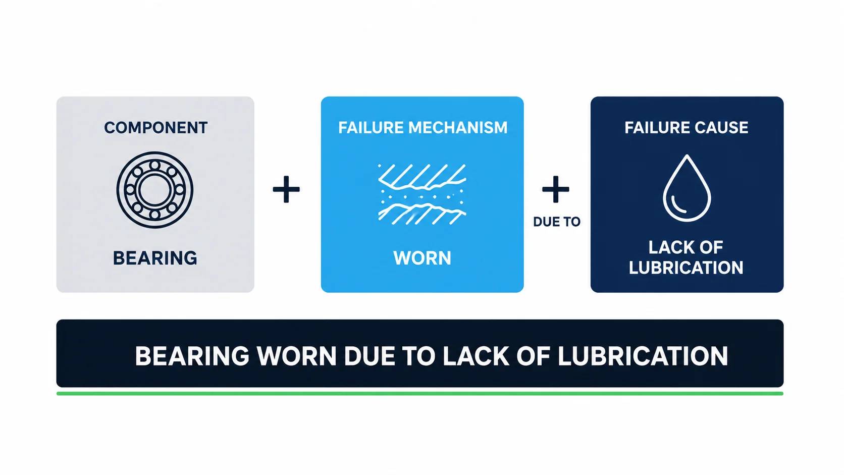
A failure mode should be written as three distinct pieces of information in a fixed order: the component, the failure mechanism, and the failure cause. The component is the specific maintainable item, the part that actually failed, not the assembly it sits inside. The failure mechanism is the physical, chemical or logical process that produced the failure, the thing you could actually observe or measure if you inspected the failed item: worn, corroded, cracked, seized, arcing, blocked. In ISO 14224:2016 terms, the failure mechanism is that process identified at the lowest achievable level in the item hierarchy, the component you would actually inspect; the failure mode is the manner in which the failure occurs as it presents one level up, at the equipment unit. Mechanism is the process observed at the component; mode is how that failure shows itself at the equipment level above it. The failure cause is the underlying circumstance that triggered or enabled that mechanism to occur: lack of lubrication, abrasive material ingress, incorrect fastening, adverse environmental exposure.
That consistency is what makes the record analysable rather than descriptive. A maintenance data set built on this structure can be queried directly: how many bearing failures this year were caused by lack of lubrication, across every pump in the fleet, regardless of who wrote the original work order.
Mechanism and cause are the two elements most often confused, and getting the distinction wrong quietly corrupts the entire failure data set. The mechanism is what you would see if you cut the component open: it is worn, or corroded, or cracked. The cause is why that happened. A structured mechanism library, aligned to ISO 14224:2016 and its Annex B grouping, groups these observable states into a small number of categories so the same word is used every time the same thing is observed, rather than every analyst inventing new wording for the same physical evidence.
- Mechanical mechanisms describe a physical change of state in a moving or load-bearing part: seized, leaking, misaligned. These are the mechanisms most often seen on rotating and moving equipment.
- Material mechanisms describe degradation of the material itself rather than a moving part: worn, corroded, cracked, pitted, deteriorated, chipped. In ISO 14224:2016 Annex B (Table B.2) wear sits under material failure rather than mechanical, because it is the material itself that is being lost. These apply as much to static structures and vessels as to rotating equipment.
- Electrical mechanisms describe an observable electrical failure state: burnt, short circuited, arcing, open circuited. These are distinct from the cause that produced them, such as an overload or a loose connection.
- Instrumentation mechanisms describe a measurement or control failure state: inaccurate, spurious output, failed to communicate. These matter as much for protective and monitoring devices as for physical plant.
- External-influence mechanisms describe a failure state imposed on the item from outside rather than arising within it, such as blocked or plugged. In ISO 14224:2016 Annex B a blockage sits under external influence, which is why it is grouped here rather than with the mechanical mechanisms above.
Restricting the vocabulary this way, rather than letting every analyst invent new terms, is what makes failure data comparable across an entire asset register instead of a collection of one-off descriptions.
Cause is also frequently confused with effect, and the distinction matters just as much. Take a clamp whose failure mechanism is loose, with a cause of incorrect fastening during the last intervention. The clamp then vibrates and eventually falls from its position.
How the Same Failure Reads One Level Up
The exact same failure is described differently depending on where you are standing in the asset hierarchy, and IEC 60812 sets out precisely how that description changes as the analysis moves up.
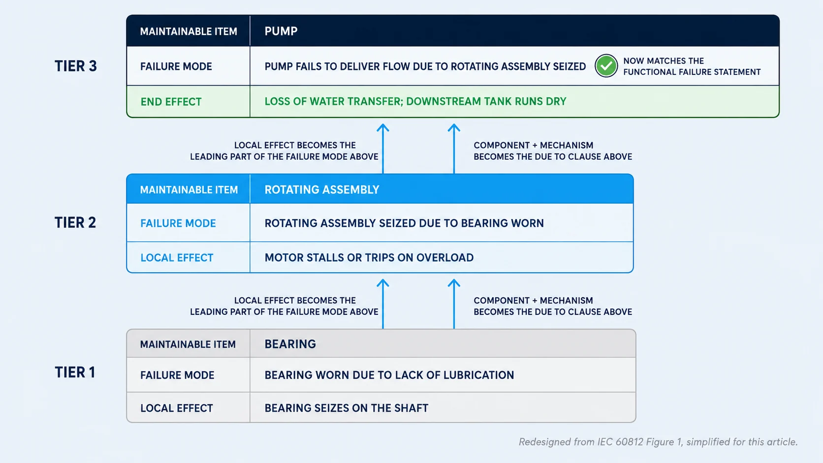
The diagram below is an original illustration based on the multi-level FMEA hierarchy described in IEC 60812. The standard sets out this relationship across a full multi-level system hierarchy in general terms; the version here is simplified to three levels and carries one worked example all the way through it, purely to make the mechanism easier to follow at a glance. The underlying logic follows the standard.
At the maintainable item level, the failure mode is the component, mechanism and cause structure covered above, and it produces a local effect: the specific, immediate consequence at or around the failed item itself. One level up, in the assembly or subsystem that item sits inside, the local effect from below becomes the leading part of the failure mode statement at that higher level, and the component-plus-mechanism from below becomes the cause folded into that same statement's due to clause, never a separate field standing beside it. IEC 60812 describes this directly: failure effects identified at a lower level may become failure modes at the higher level, and failure modes at the lower level may become failure causes at the higher level. The analysis proceeds bottom-up, one level at a time, and each level's local effect and failure mode become the fuel for the level above it.
That convergence at the top, where the failure mode and the functional failure become the same statement, is expected and correct. It is IEC 60812's own description of how a system hierarchy works, and it is exactly why an analyst working at equipment level, and a planner working at component level, can both be technically correct while describing what looks like a completely different failure. Knowing which level you are writing at, and carrying the mechanism and cause language consistently up through each level rather than starting fresh at every layer, is what keeps the whole analysis traceable from a functional failure on a P&ID down to a single worn bearing on a work order.
Question Four: Writing Effects That Are Specific, Not Vague
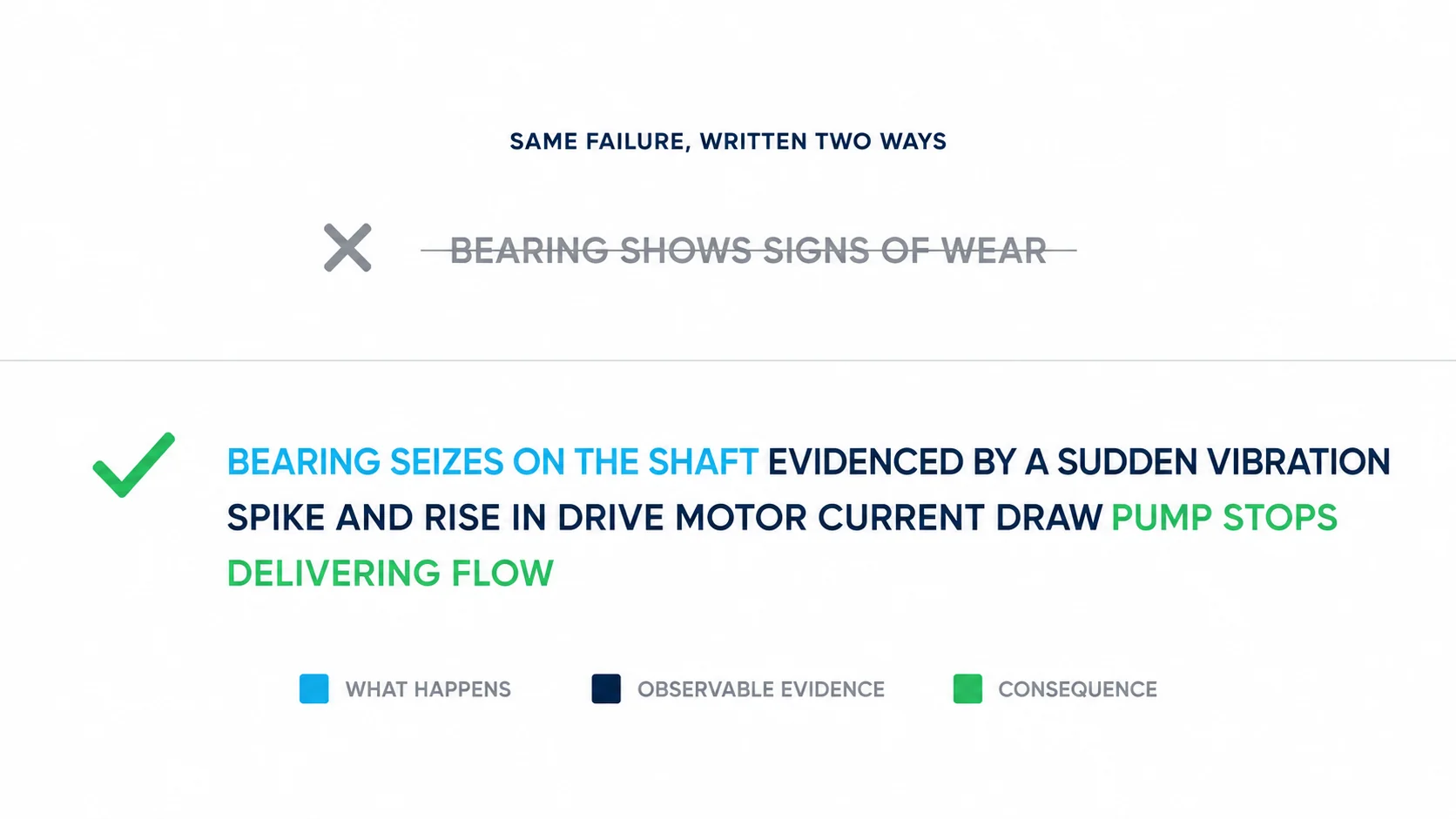
An effect written as may affect performance has told the reader nothing they could not have guessed, and it is one of the clearest signs that an FMECA was completed to satisfy a checklist rather than to be used.
A local effect should describe exactly what happens at or near the failed item, in observable, specific terms: a vibration alarm triggering at a stated value, a trip occurring within a stated time, a noise or a leak with a stated severity. The end effect, sometimes called the system effect, should describe what the business, the operator or the person downstream of the asset actually experiences, in terms that connect directly to the consequence categories used in question five: an amount of lost production, a duration of unavailability, an unplanned shutdown, a safety exposure, an environmental release, or in the least severe case, simply the cost of the repair itself with nothing else affected. Writing effects with this level of specificity is what makes the consequence category that follows a defensible judgement rather than a guess dressed up as analysis.
Question Five: Failure Consequences
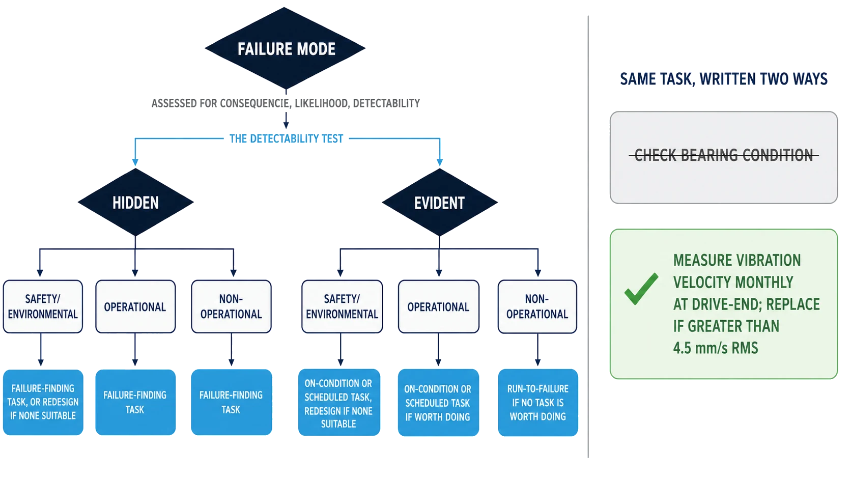
Question five is where RCM makes its most distinctive contribution, and getting there properly means resisting the urge to jump straight to a decision tree and read an answer off it. Before any tree is applied, the failure mode needs three separate judgements made against it: its consequence, its likelihood, and its detectability.
These three are exactly what Failure Mode, Effects and Criticality Analysis was built to combine, drawn from the same severity, occurrence and detection foundation introduced earlier in this piece, and question five simply takes that evidence and runs it through a decision structure rather than a single blended score. Consequence is read directly off the effects written in question four, not invented fresh at this stage: a local and end effect written with real specificity is what tells an analyst whether a failure mode is a safety exposure, an environmental release, a production loss, or simply a repair bill. Likelihood is the frequency or probability of this specific failure mode, drawn from site history, OEM reliability data or, where neither exists, a defensible engineering judgement, never treated as a single constant applied to every failure mode on the asset regardless of how different their actual mechanisms are. Detectability is how reliably a warning of this failure mode would be picked up before it reaches functional failure, and it carries more weight in the outcome than it is usually given credit for: getting detectability wrong is one of the most common ways a maintenance program ends up with the wrong task type on the plan. A failure mode with genuinely poor detectability cannot be managed with a condition-based task no matter how attractive that option looks on paper, because there is nothing reliable to monitor, and assigning one anyway produces a task that looks proactive on a maintenance plan while doing nothing to actually catch the failure before it happens.
That third judgement, detectability, is not the same as the RCM decision logic's own first split, even though the two are easy to run together. That first split, hidden against evident, asks a different question: will the loss of function become apparent to the operating crew under normal conditions if this failure mode occurs on its own. It is not a measure of how much advance warning the failure gives. Evident failures are apparent to the operating crew under normal conditions when they occur. Hidden failures are not: they most often sit in protective devices, standby equipment and instrumentation, carry no immediate consequence on their own, and become apparent only when a further failure occurs, removing the protection that prevents a second, often much more serious, event.
The second stage asks, within each of those groups, whether the failure affects safety or the environment, whether it affects operational capability such as output, quality or service on top of the direct repair cost, or whether it affects only the cost of repair with no broader operational consequence. That two-stage classification, hidden versus evident, cross-referenced against safety and environmental, operational, and non-operational consequences, is what determines how rigorously each failure mode must be managed and what level of risk tolerance the organisation is willing to accept.
Why Fixed Intervals Fail Most Failure Modes
The instinct to set a fixed maintenance interval and leave it unchanged for the life of the asset is one of the most expensive habits in an asset-intensive operation, and it is question six, what can predict or prevent the failure, that RCM uses to correct it.
Reliability research into the relationship between age and failure identified six distinct patterns of conditional failure probability. Two show a clear wear-out point where the probability of failure rises sharply with age. A third shows a steady increase with no distinct wear-out point. The remaining three show either a constant, largely random probability of failure at any age, or an infant mortality pattern where failure risk is highest shortly after intervention and then settles to a low, steady level. Across the equipment populations these patterns were studied on, only a minority of failure modes, commonly cited at around eleven per cent, showed an age-related pattern that genuinely benefits from a fixed age or usage limit. The remaining majority do not, and for infant mortality patterns, imposing a fixed overhaul interval can introduce failures rather than prevent them.
This is why on-condition tasks dominate a well-built RCM output rather than blanket overhauls. Most failure modes give some warning before they become a functional failure, a change in vibration, temperature, pressure, wear debris, or visual condition. The interval between when that potential failure becomes detectable and when it deteriorates to a functional failure, known as the P-F interval, is the window available to intervene, and monitoring within that window, rather than replacing on a fixed calendar, is what a sound proactive task is built around wherever the failure mode allows it.
Questions Six and Seven: Writing Tasks That Execute the Same Way Every Time
A proactive task is only proposed if it is technically feasible, meaning it can actually detect or prevent the failure or reduce its consequences, and worth doing, meaning the risk or cost it removes justifies the direct and indirect cost of doing the task.
- On-condition tasks monitor for evidence that a failure is in progress, using the window between potential and functional failure to schedule intervention before consequences occur. These are the preferred option wherever a detectable warning exists.
- Scheduled restoration and scheduled discard tasks work on a fixed interval, restoring or replacing an item regardless of its condition. These are only justified where the failure mode follows a genuine age-related pattern and the interval is set safely below the age at which the conditional probability of failure begins to rise.
- Failure-finding tasks apply only to hidden failures. They periodically check whether a protective function has already failed, and the interval is set to keep the probability of the multiple failure, the hidden failure coinciding with the demand it is meant to protect against, acceptably low. The consequence assessed for a hidden failure is the consequence of that multiple failure, not of the hidden failure on its own.
- One-time change, or redesign, alters the physical configuration of the asset, the process, or the way it is operated. It becomes mandatory, not optional, wherever a hidden or evident failure carries a safety or environmental consequence and no proactive task can be found.
- Run-to-failure is a deliberate, analysed decision, not a default born of neglect. It is the correct outcome wherever a failure has only operational or non-operational consequences and no proactive task is cost-effective.
The task selected this way is the primary task, and how precisely it is written determines whether it produces consistent, trustworthy data or a different result every time a different technician performs it. A primary task should specify the action, the exact component or location, the method or instrument used to take the reading, the frequency, and a numeric acceptable limit that triggers the next step.
That acceptable limit is also what defines the default or corrective action, the response to question seven. The default action should state precisely what triggers it and precisely what happens next within a timeframe the P-F interval can actually support.
Every acceptable limit in a maintenance program should carry that same level of precision: a number, a unit, a measurement method, a measurement location, and an unambiguous next action, written with the same discipline a calibrated work instruction demands on a production line, where two operators following the same instruction are expected to reach the identical outcome every time. A task written any less precisely has not really been selected by the RCM process at all. It has simply been renamed.
Closing the Loop: From Analysis to the CMMS
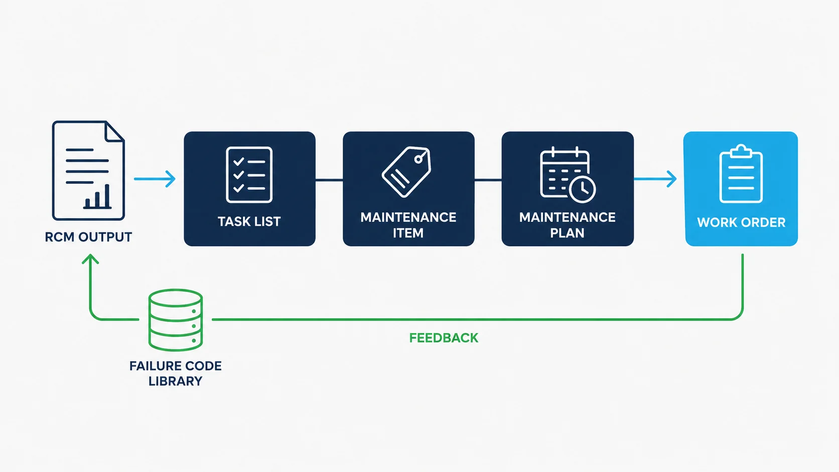
An RCM output that lives in a spreadsheet has delivered half its value. The other half depends on how faithfully it is translated into the system that actually schedules and executes the work.
Criticality determines where this rigour is applied. The highest-criticality equipment justifies full FMECA and RCM treatment, function by function and failure mode by failure mode. Lower-criticality equipment can be managed through a streamlined analysis or a proven default strategy, so the cost of the methodology is spent where it earns a return.
Each selected task then needs a home in the CMMS, whether that is SAP PM, Maximo, or an equivalent platform. A task list carries the structured work instructions and operations, written with the same precision described above. A maintenance item defines the specific asset object the task applies to and its scheduling parameters. A maintenance plan is the recurring trigger, tied to time, meter reading, or condition input, that generates the work order or notification automatically. The failure code hierarchy captured during the FMECA stage, the same component, mechanism and cause structure used throughout this analysis, should map directly onto these same task lists and maintenance items, so that when a real failure eventually occurs and a technician closes out the work order against a structured code rather than free text, that record feeds straight back into the evidence base the original analysis was built from.
Making It a Living Program
An RCM analysis signed off once and never revisited quietly decays into the same kind of inherited guesswork it was built to replace.
A living program is reviewed when new failure data contradicts an original assumption, when a redesign changes or removes a failure mode, when the operating context changes materially, or when a criticality re-rating changes which failure modes justify full analytical rigour. The maintenance strategy this process produces belongs inside the Asset Management Plan as the documented method for managing each asset's failure modes, keeping a clear line of sight from board-level asset management objectives down to the specific task scheduled against a specific piece of equipment.
Run this way, FMECA and RCM measurably improve the operational metrics a COO or plant manager is judged on: fewer unplanned failures with operational consequences lift Overall Equipment Effectiveness, structured failure codes shorten Mean Time To Repair by pointing a technician straight at the likely cause, and tasks scaled to actual consequence rather than uniform caution keep maintenance spend proportionate to the risk it is managing. That is the return on doing the analysis properly, at every level of it: every task on the plan can be traced, question by question, back to a function, a failure mode, and a decision, not an inherited number nobody can explain.
For the wider planning context this maintenance strategy sits inside, see asset lifecycle management planning, and for how these methods fit together across an asset base, the Shivaan Asset Management framework.
Frequently asked questions
What is the difference between FMECA and RCM?
FMECA answers what can fail, how it fails, and how severe that failure is. It identifies each function, each way that function can fail, and what happens when it does, then ranks those failure modes by severity, frequency and detectability. RCM picks up where FMECA leaves off. It does not re-identify functions or failure modes from scratch; it uses the FMECA output as its evidence base and applies a structured decision process to select the failure management policy for each failure mode, which may be a scheduled task, a redesign, or a deliberate decision to run the asset to failure.
How should a failure mode be written?
As three distinct pieces of information in a fixed order: the component, the failure mechanism, and the failure cause, joined into one continuous statement by the words "due to". The component is the specific maintainable item that actually failed, not the assembly it sits inside. Bearing Worn due to Lack of Lubrication is the structure; pump failed or bearing fault is not, because a technician, a planner and a reliability engineer will each interpret those differently.
What is the difference between a failure mechanism, a failure cause and a failure effect?
The mechanism is what you would see if you cut the component open: worn, corroded, cracked, seized, arcing, blocked. The cause is why that happened: lack of lubrication, abrasive material ingress, incorrect fastening, adverse environmental exposure. The effect is what happens afterwards. Take a clamp whose mechanism is loose, with a cause of incorrect fastening during the last intervention: the clamp then vibrates and eventually falls, and that vibration and fall are the effect of the failure, not the cause of it. Mechanism and cause are the two most often confused, and getting the distinction wrong quietly corrupts the entire failure data set.
Why do fixed maintenance intervals fail most failure modes?
Reliability research into the relationship between age and failure identified six distinct patterns of conditional failure probability, and only a minority of failure modes, commonly cited at around eleven per cent, showed an age-related pattern that genuinely benefits from a fixed age or usage limit. The remaining majority do not, and for infant mortality patterns, imposing a fixed overhaul interval can introduce failures rather than prevent them. This is why on-condition tasks dominate a well-built RCM output: most failure modes give some warning, and the interval between when that warning becomes detectable and when it deteriorates to a functional failure, the P-F interval, is the window available to intervene.
What makes a maintenance task precise enough to execute the same way every time?
A primary task should specify the action, the exact component or location, the method or instrument used to take the reading, the frequency, and a numeric acceptable limit that triggers the next step. Measure bearing housing vibration velocity at the drive-end horizontal position monthly, using a handheld vibration analyser, and raise a corrective work order if the reading exceeds 4.5 millimetres per second RMS is a task. Check bearing condition is not: three technicians asked to check bearing condition will produce three different judgements from three different inspections.